Thursday, December 30, 2010

TCAP

The following topics provide an overview of TCAP and how it is used to provide enhanced network services:

  • Generic service interface
  • Role of TCAP in call control
  • TCAP within the SS7 protocol stack
  • Transaction and component sublayers

Generic Service Interface

TCAP is designed to be generic to accommodate the needs of a wide variety of different services. Some common services that use TCAP include number translation services, such as Enhanced 800 Service and Local Number Portability (LNP). Other examples of TCAP users are Custom Local Area Signaling Services (CLASS), Mobile Wireless, and Advanced Intelligent Network (AIN) services. Figure below shows how TCAP uses standardized components as the basic building blocks for services across network nodes.

10fig01.gif

Figure: Standardized Components Used to Create a Generic Interface

Most TCAP services can be viewed as a dialogue of questions and answers. A switch needs additional information that is associated with call processing, or with a particular service that causes it to send a TCAP query that requests the needed information. As shown in Figure below, the answer returns in a TCAP response, which provides the necessary information, and normal call processing or feature processing can resume. The query for information can be sent to a Service Control Point (SCP) or to another SSP, depending on the type of service and the information required. The SCP is an SS7-capable database that provides a centralized point of information retrieval. It typically handles number translation services, such as toll-free and LPN; however, SCPs are also used for a number of additional IN/AIN services.

10fig02.gif

Figure: Simple Query and Response

Role of TCAP in Call Control

TCAP is used to provide information to SSPs. This information is often used to enable successful call completion, but TCAP is not involved in the actual call-setup procedures. This interaction between the service information provided by TCAP and the circuit-related protocol that performs the call setup occurs at the application level, not at the SS7 protocol layer.

TCAP Within the SS7 Protocol Stack

As shown in Figure below, TCAP is at level 4 of the SS7 protocol stack. It depends upon the SCCP's transport services because TCAP itself does not contain any transport information. First, SCCP must establish communication between services before TCAP data can be delivered to the application layer. Refer to Chapter 9, "Signaling Connection Control Part (SCCP)," for more information on SCCP's transport services. TCAP interfaces to the application layer protocols above it, such as the ITU Intelligent Network Application Part (INAP), ANSI AIN, and ANSI-41 Mobile Switching to provide service-related information in a generic format. The application layer that passes information down to be encapsulated within TCAP is known as a Transaction Capability User (TC-User). The terms application, service, and TC-User are used interchangeably.

10fig03.gif

Figure: TCAP Within the SS7 Stack

Thursday, December 23, 2010

SS7


SS7 is a signaling network and protocol that is used to bring telecommunications networks to life. Calls, roaming and messaging, and converged voice/data services, call Waiting, are few of the vast number of services that SS7 is used in the communications network.

There are many combinations of protocol stacks. It depends on whether SS7 is used for cellular-specific services or intelligent network services, whether transportation is over IP or is controlling broadband ATM networks instead of time-division multiplexing (TDM) networks, and so forth. SS7 stack is comprised of following protocols.
  • Message Transfer Parts (MTP 1, 2, and 3)
  • Signaling Connection Control Part (SCCP)
  • Transaction Capabilities Application Part (TCAP)
  • Telephony User Part (TUP)
  • ISDN User Part (ISUP)

ss7 Stack
MTP
This comprises the functions to transport information from one Service Point to another. The MTP transfers the signaling message, in the correct sequence, without loss or duplication, between the Service Points that make up the SS7 network.

MTP3
MTP3 performs two functions:

  • Signaling Message Handling (SMH)— Delivers incoming messages to their intended User Part and routes outgoing messages toward their destination.
  • Signaling Network Management (SNM)— Monitors linksets and route sets, providing status to network nodes so that traffic can be rerouted when necessary.

TUP and ISUP
TUP and ISUP sit on top of MTP to provide circuit-related signaling to set up, maintain, and tear down calls.

SCCP
The addition of the SCCP provides a more flexible means of routing and provides mechanisms to transfer data over the SS7 network. Such additional features are used to support noncircuit-related signaling, which is mostly used to interact with databases (SCPs).

Enhanced routing is called global title (GT) routing. It keeps SPs from having overly large routing tables that would be difficult to provision and maintain.


TCAP
TCAP allows applications to communicate with each other (over the SS7 network) using agreed-upon data elements. These data elements are called components. Components can be viewed as instructions sent between applications.

Wednesday, December 22, 2010

Sigtran Stack


The SIGTRAN Stacks implements the full power of SS7 Application Programming Interface's (API's) allowing unlimited user applications to seamlessly communicate between the legacy and Next Generation Networks (NGN). It provides a client signaling stack in an IP-based Next Generation Network element that enables it to communicate over IP network using SIGTRAN defined architecture.

With the SIGTRAN stack, consumers are free to choose from several of the defined SIGTRAN protocol layers. Each layer has its own unique characteristics that make it applicable to a given situation.

For each, the SS7 stack is substituted at one of its well-defined layers with a packet transport replacement. By moving up to higher layers higher in the stack, more of the legacy SS7 concepts can be eliminated and replaced with flexible packet and IP protocol routing capabilities. Because SIGTRAN is an industry standard, it allows customers to interoperate in a multi-vendor environment.

The key components in the SIGTRAN achitecture are as follows:
  • MGC–Media Gateway Controller, responsible for mediating call control (between the SG and MG) and controlling access from the IP world to/from the PSTN.
  • SG–Signaling Gateway, responsible for interfacing to the SS7 network and passing signaling messages to the IP nodes.
  • MG–Media Gateway, responsible for packetization of voice traffic and transmitting the traffic towards the destination.
  • IP SCP – an IP-enabled Service Control Point (SCP). This exists wholly within the IP network, but is addressable from the SS7 network.
  • IP Phone–generically referred to as a “terminal.”
Sigtran Architecture


Sigtran Protocol Stack


Sunday, December 19, 2010

USSD Gateway

USSD gateway stands for Unstructured Supplementary Service Data Gateway which is simply a router, which routes USSD messages from the signaling network to service applications and back. It's also identified as a signalling node which has it's own internal point code as well as own global title.

USSD is a session based protocol used by GSM cellular telephones to communicate with the service provider's computers


USSD uses Signaling channels to transmit bi-directional data between the mobile and the application defined by the operator

USSD messages are used for many things such as
  • Notifying
  • WAP browsing
  • Providing menus
  • Activating a mobile service
  • Configuring a subscriber quickly and directly
  • Location based content services

The network architecture of the USSD Gateway is as follows

There are many advanages of USSD services when compared to the sibling service SMS
  • Innovative solution - Menu based
  • Immediate push and pull service
  • Ease of use for the subscriber
  • Easy to validate to the operator
  • Longer message length then SMS
  • Easy extension possibility
  • Can be used by 99.99% of the mobiles which exist for today
  • Does not require any modifications to the SIM

In USSD services there are short cuts as well. Rather than accessing a service using for an exampe *500#, and then browsing through the menu, someone may be able to access the ultimate service intended to use directly by, *500*3*2*86568855487*9700*123#. This is another advantage of USSD services where a knowledged user would be capable of performing the task faster.

For USSD implementations, there are two ways possible. That is via SS7 technology or using Sigtran. The pros and cons differ in each case

SS7
Advantages:
  • The bandwidth is guaranteed ensuring optimal quality of service
  • All operator equipment is reputed to be MTP (standard) compatible

Disadvantages:
  • The platform must be hosted near the operator's equipment (STP or HLR)
  • SS7 cards expensive to buy
  • The bandwidth is limited to a few dozen COC of 64Kb/s

Sigtran
Advantages
  • Flexibility and the possibility of having the Gateway away from the operator's site, directly with the Service Provider via a secure VPN network.
  • No costly cards
  • The platform can be hosted on a site far from the operator's equipment
  • The bandwidth is no longer limited but can reach hundreds of Mbit/s
  • Items may be connected in stars and not point to point, allowing direct virtual connection and eliminating certain limitations of network items.
  • A multinational operator may see their various national networks as a large scale intranet and pool their network equipment.
  • The redundancy of the equipment is transparent, several pieces of equipment may have the same address and share the load invisibly for the transmitter.
  • Just one SCTP packet can contain several messages ? less routing cost

Disadvantages
  • The bandwidth is not as guaranteed
  • All equipment is not yet compatible with Sigtran
  • Troubleshooting is more complex - IP path and by the number of messages in a frame


Wednesday, December 15, 2010

Commonly used techniques for User Interface Design

Many technology improvements rely upon the User Interface just to make sure that everything that the technology could offer is visible through the User Interface. Any superior technology will not be applied unless it is used with the practical context, that is via a UI. The key acceptance feature is the UI which gives it a valuable position in software engineering life cycle. For greatest efficiency and cost effectiveness, this working relationship should be maintained from the start of a project to its rollout. Following are set of features in which develpers make common mistakes.

1. Interface Elements on demand
This feature is basically reduce number of buttons or options user can see on the screen. Same options can be provided to user only when it is needed. This will ensures the neatness of the system and well structred.

2. Specialized, required content
Interface should be designed in such a way that, the best, most approprite element for the moment is used. Basically for an "on", "off" switch there is no point of providing with boolen True/False value. Calendar would be useless unless a calendar can be popped up.

3. Disabling pressed buttons
This is another common mistake where users can go wrong. Simply the idea is, user should be aware about the current condigion.

4. Shadow around model windows
Highlighting model windown would give the oppertunity of highlighting the window from the background with the feeling that it's a seperate screen for the viewers who used the interface.

5. Empty states leading your way
It is to writing erasable text inside empty states, text boxes in order to improve the awareness of the user about the content of the system. E.g.: Facebook "What's on your mind"

6. Hyperlinks
It is always adviced to keep the hyperlinks as it is since it might come in very handy when it comes to furthur reference.

7. Space for extendability
One of the most common problem that the developers are facing when it comes to the UI issues is that change of requirements would end up in a place where they will have to work everything from the begining. To avoid this problem, space should be kept for extendability and furthur changes.

Avove mentioned techniques are only some from a whole lot and there are many more things to be considered in User Interface design especially including the user acceptance testing part because that would be the ultimate place where it would be checked.

Thursday, December 9, 2010

SMS Elements

Short message service comprised of seven elements which helps Service Center in receiving and sending Short messages in accordance with the standards. These are common set of standards agreed by the mobile phone manufacturers and the same set of standards are used by the Service centers as well. Any equipment other than a mobile phone such as a GSM modem should adhear to these standards if they want to send SMS.
Following is a list of those elements

Validity-Period;
Service-Centre-Time-Stamp;
Protocol-Identifier;
More-Messages-to-Send;
Priority;
Messages-Waiting;
Alert-SC

Validity period
Validity period is the element which is decided by the Short Messaging entity and inserted in the SMS-SUBMIT which is to be sent to the Short Message Service Center (SMSC). This value let SMSC decide how long the message should be kept on retrying to send to the intended receipient if not delivered. If SMSC has a default validiy period less than the value specified by the SME, then the parameter "Tp-Validity-Period" is overwritten to avoid the infinity waiting of message in SC.

Service center time stamp
Time stamp is the service element which is inserted by the SMSC in the SMS-Deliver message which is sent to the receipient. It gives an idea to the receiver the arrival time of the message to the SMSC. The parameter "TP-Service-Centre-Time-Stamp"should also be adjusted in accordance with the receivers time zone difference and a count which is of 15 minutes intervals is used for this.
E.g. GTA +5.30= 330 minutes, 330/15=22, so GTA +5.30 is indicated by the code 22.

Protocol identifier
Protocol identifier is the element in which the protocol used by a higher layer is identified at transfer layer. It includes in all of the following message types. SMS-SUBMIT, SMS-SUBMIT-REPORT for RP-ACK, SMS-DELIVER DELIVER, SMS-DELIVER-REPORT for RP-ACK, SMS_STATUS_REPORT and SMS-COMMAND TP-Protocol-Identifier (TP-PID).

More messages to send
This is the parmeter used in SMS-DELIVER to indicate the Mobile Station by the Service Center that there are more messages waiting in the SC to be sent to the MS. TP-More-Messages-to-Send (TP-MMS) is the paramer name and this is a boolen value which indicates the true/ false situation of the more messages are there or not. If not --> 0 and if yes --> 1.

Priority
Priority is the paramer entered by the Sc or the MS to indicate the priority of delivering the message. A message is not attempted continuously to send if it is not an priority SM. If a non priority SM doesn't get delivered due to the absense of the mobile station, it is informed to the HLR asking to notify SC once the MS become available. But for priority SMs it is being continuously attempted to send the message by the SC itself.


Message waiting
In the above explined delvery procedure of non priority messages, HLR neeeded to be informed that there is a message waiting in the SMSC to be sent to a particular reciepient. The service element used for this task is Messages-Waiting-Indication (MWI) and it comprises of Messages-Waiting-Data (MWD), the Mobile-station-Not-Reachable-for-GPRS (MNRG), the Mobile-Station-Not-Reachable-Flag (MNRF), the Mobile-Not-Reachable-Reason (MNRR) and the Mobile-Station-Memory-Capacity-Exceeded-Flag (MCEF) located in the HLR; the Mobile-station-Not Reachable-for-
GPRS (MNRG) located in the SGSN, and the Mobile-Station-Not-Reachable-Flag (MNRF) located in the VLR.

Alert SC
Alert SC is the element used by HLR to inform SC that the availability of the mobkile stations which were unavailble before due to:

1. Delivery attempt has failed because the MS is not reachable or because the MS memory capacity was exceeded; and
2. Not recognized by the PLMN:
a) to have resumed operation (e.g. to have responded to a paging request); or
b) to have memory newly available (which implies that the mobile is reachable).

Wednesday, December 8, 2010

DRBD - Distributed Replicated Block Device


DRBD stands for Distributed Replicated Block Device which actually means nothing shared but replicated in simple terms. Block devices may be hard disks, partitions or logical drives. DRBD is a part of the Lisog open source stack initiative which is an German not for profit organization which was found to each other.


DRBD is a distributed storage system for GNU/Linux platform and it is consist of
    • Kernal module
    • User space management applications
    • Shell scripts
Normally DRBD is used in high availability clusters and very much similar to RAID1 set up, except that DRBD runs over a network.

Raid 1 has following features
    • Creates an exact copy or mirror of a set of data on two or more disks
    • Good when read performance and reliability are more important than data storage capacity
    • Really good for reliability. E.g. Two idential disks drive with 5% probability that a disk would fail then the the total probability of system failing is (0.05)^2 = 0.0025, that is 0.25%.

What DRBD does
Mirroring
Works on the top of the block device, i.e hard disk partitions or virtual machines logical volumes
Mirror each and every data block wirtten to a disk
DRBD mirrors data
  • In real time - Continuous replication
  • Transparently - With applications knowing that data are stored more then one computer
  • Synchronously or asynchronously
    • Synchronous - Writing would be completed after all the replications are completed
    • Asynchronous - Writing would be completed once the local data store is updated, but before the peers are updated


Data Accessability
File accessability in the file system

Feature list
  • May be used to add redundancy to existing deployments
  • Fully synchronous, memory synchronous or asynchronous modes of operation
  • Masking of local IO errors
  • Shared secret to authenticate the peer upon connect
  • Bandwidth of background resynchronization tunable
  • Automatic recovery after node, network, or disk failures
  • Efficient resynchronization, only blocks that were modified during the outage of a node.
  • Short resynchronization time after the crash of an active node, independent of the device size.
  • Automatic detection of the most up-to-date data after complete failure
  • Integration scripts for use with Heartbeat
  • Dual primary support for use with GFS/OCFS2
  • Configurable handler scripts for various DRBD events
  • Online data verification
  • Optional data digests to verify the data transfer over the network
  • Integration scripts for use with Xen
  • Usable on LVM's logical volumes. Usable as physical volume for LVM
  • Integration scripts for LVM to automatically take a snapshot before a node becomes the target of a resynchronization
  • Dependencies to serialize resynchronization, in case of default all devices in parallel
  • Heartbeat integration to outdate peers with broken replication links, avoids switchovers to stale data
  • Many tuning parameters allow to optimize DRBD for specific machines, networking hardware, and storage subsystem
  • Integration scripts for use with RedHat Cluster
  • Existing file systems can be integrated into new DRBD setups without the need of copying
  • Support for a third, off-site node for disaster recovery
  • Support for compression of the bitmap exchange
  • Support for floating peers in drbdadm
  • Feature complete OCF Heartbeat/Pacemeker resource agent
  • Resource level fencing script, using Pacemaker's constraints
  • Supports TCP/IP over Ethernet, SuperSockets over Dolphin NICs and SDP over Infiniband

Friday, December 3, 2010

SMS Email Inter-working

SMS to email and email to SMS conversion is a popular concept which is available as for the current condition. This was first developed as an application which is built on top of the SMSC. Any text message or email is sent to the application and application handled the logic thereafter.

But as with the increasing trend of use of this service it has come to a level where this service is included in the SMSC itself rather than using it in a seperate application. Including the service in the SMSC will provide some advantages rather than having it as an application. The time spent on
To start connection between SMSC and applicaiton
The connection handling, authorizing procedures
Complex acknowledgement processes

can be eliminated by integrating the service inside the SMSC.

There are some basic things that should be taken care in the process of providing a successful service.

1. Basic format
There should be basic format where users using this service must adhear to in order to perform successful conversion between sms and electronic mail. There would be two seperate formats for MO flow and MT flow
E.g.
MO - ]
MT - ]
In the above examples MO represents the text to email conversion whereas in MT it represents the email to text conversion

Some features like Carbon Copy wont be supported in this formats since it would restrict the capacity of the messages

Subject, real name of the sender, optional control flags and message concatenations would be treated as optional features.

Unlike in usual emails, name should be entered manually by the user.
]#[##]#

Subject of the email also should be inserted according to the format like in following examples
]() or ]###

Optinal controller flags are also available to use the features like email signatures, predefined texts etc. The important thing to remember is all the optional controller flags are pre defined and would depend on the email service provider.

Thursday, December 2, 2010

TP-Message-Refernce

The TP-Message-Reference field gives an integer representation of a reference number of the SMS-SUBMIT or SMS-COMMAND submitted to the SC by the MS. The MS increments TP-Message-Reference by 1 for each SMS-SUBMIT or SMS-COMMAND being submitted. The value to be used for each SMS-SUBMIT is obtained by reading the Last-Used-TP-MR value from the SMS Status data field in the SIM card and incrementing this value by 1. After each SMS-SUBMIT has been submitted to the network, the Last-Used-TP-MR value in the SIM is updated with the TP-MR that was used in the SMS-SUBMIT operation. The reference number may possess values in the range 0 to 255. The value in the TP-MR assigned by the MS is the same value which is received at the SC.

In the case where no response or an RP-ERROR with an appropriate cause value is received in response to an SMS-SUBMIT, then the MS shall automatically repeat the SMS-SUBMIT but must use the same -MR value and set the TP-RD bit to 1. The number of times the MS automatically repeats the SMS-SUBMIT shall be in the range 1 to 3 but the precise number is an implementation matter. The automatic repeat mechanism should be capable of being disabled through MMI.

If all automatic attempts fail, the user shall be informed. The failed message shall be stored in the mobile in such a way that the user can request a retransmission using the same
TP-MR value, without the need to re-enter any information. Such storage need only be provided for a single failed message, i.e. the one most recently attempted.

The SC should discard an SMS-SUBMIT which has the TP-RD bit set to a 1 and which has the same TP-MR value as the previous SMS-SUBMIT received from the same originating address. In the case of a discarded SMS-SUBMIT, the SC should respond with an RP-ERROR, in which case the RP-ERROR shall include a SMS-SUBMIT-REPORT with TP-FCS indicating “SM Rejected – Duplicate SM”. In some cases, for backward compatibility with earlier phases and versions of this specification, the SC may be configured to respond with an RP-ACK.

The SMS-STATUS-REPORT also contains a TP-Message-Reference field. The value sent to the MS shall be the same as the TP-Message-Reference value generated by the MS in the earlier SMS-SUBMIT or SMS-COMMAND to which the status report relates.

Tuesday, November 9, 2010

Saturday, November 6, 2010

Oracle Real Application Clusters (RAC)

Real application clustering is a method where multiple instances of oracle accessing a single data store simultaneously, with cache synchronization according to oracle global cache management technology (cache fusion).

Why actually oracle RAC is needed is worth considering. Without RAC in an environment where applications busy accessing the physical database, there is a higher chance of failure. And the reliability factor as well as the scalability factor are also considerably low. Because of these needs, RAC emerged where it could bring about a solution to the above mentioned.


Architecture is arranged in such a way that multiple nodes access the physical data sore concurrently, which can be exceeded up to eight nodes. This provides a complete clustering solution where data between applications are synced, monitored and manged. And it also restart the oracle instances.

In the oracle cluster any node is allowed to update data on the single physical database, SAN (Storage Area Network). The real advantage of this is all the nodes access the same set of data which is updated and changed live. In almost all the value critical applications such as bank systems, this is really important feature since live data is needed for processing.

Since maintaining a single database, it makes the management and administration of the database easy. Even though it shares the data store, in each database servers, it has it's own, application, logs, operating system, and database instance. What is shared here is the all the data and meta data which affects the real data.

RAC is capable of handling fail overs and load balancing as well. In an situation of failure, it can balance the load among the other servers and users won't feel any difference in the service offered to them.

Cache fusion is also another important feature associated with RAC in which instance's cache is copied to a global cache as any node can access the information fast. This allows any server to get the most updated data without actually going to the physical disk. This is like information having in cache memory of a computer.

Benefits of this RAC technology includes, reliability, recoverability, error detection and continuous operation which comes under the main category of high availability and also it supports scalability.

Friday, November 5, 2010

Oracle Database Architecture

For allmost all the application, written today, needs a database to keep the information centralized. For this purpose, a database management system may be used which will help to manage data effectively and efficiently with fast response time.

Oracle is one such famous database management system which supports many activities and supports the required efficiency and accuracy from the architecture itself.

Oracle Relational Database Management System (RDBMS) is consists of two major layers which supports for high response rate: physical layer and logical layer.

What actually happens in the physical layer is, it stores the data as it is, without any relationship among data. In simple terms if anyone peeps in to the physical layer he/she might see some data blocks bt without any idea of relationship among them.

Physical layer consists of three different file types, data files, redo log files and control files. Data files contain the information about the database, basically the raw data which resides in the database. There can be one or more datafiles present in the database and having many of them will lead to enhanced performance of the RDBMS. The maximum amount of datafiles which can be created is limited by the oracle from the variable, "MAXDATAFILES".

Second type of files in the physical layer is the "redo log" files. These files contain the data which can be used to recover the database in a situation of a database failure. It is more like a log which has all the changes of the system. And the important fact to remember is, if the redo log files are lost there is no way of recovering the database. Important to make sure the safety of these files.

Control files are the third type of files in the physical layer which has the information needed to start an instance of the oracle database. For an example it has the information of location of the redo log file etc. Since this is important aspect of the database architecture, multiple copies ot the file is saved in different places.

In logical layer of the orcle architecture, it consists of two layers inside, tablespaces and database schema. The main purpose of the tablespace is to logically group the data. In applications wt we do is to access tables in the database. That table relationship is created by this logical layer which will logically integrate the data and show the applications the relationship in data. Using this logical layer make the administration easy. And also it provide the facility for the data blocks, data files to be spread over a wide diskspace rather than having them in the same disk. Having datafiles in seperate disks have a really good advantage on performance factor as it will cause less traffic in I/O.
Some of the important concepts in this tablespace are "data block", "extent" and "segment". Data block is the actual physical size of one data block in oracle database. The contiguous data blocks are called as extent whereas a set of extents is called as segment.

Database schema is the next layer inside logical layer where the oracle instances dominate. Oracle instances are made via the System Global Area (SGA) and it is a combination of background processes and memory buffers.
SGN referes to share information where data plus control information resides in that. Program Global Area (PGA) is another word that comes along with SGA. Other than the fact that SGA is shared information and PGA is about non shared information most of things in these two are similar.

Thursday, November 4, 2010

Sunday, October 31, 2010

Types of Clustering in computing

As explained in the previous post, clustering is categorizing set objects according to the similarity factor and there were three main categories. In this post the types of clustering is discussed.

There are two main types of clustering: Hierarchical and Partitional. In Hierarchical type what it does is arranging the elements according to an hierarchy whereas partitional, partitions the elements into groups.

In hierarchical type, it consists of two methods again, Bottom-up and Top-down. In top down, it categorize the total set in to two and then the each result will continue doing that according to a similarity value. In bottom up it makes couples according to the similarity. This is a very expensive method since it involves events with each and every data. These similar couples will make a hierarchy and hence called bottom up hierarchy.

The next type, partitional will partition the total element set to the clusters. The main difference is user input about the number of clusters is required here which will make it feasible to define any number of clusters. Randomly placed elements will be moved towards the center of the clusters in the process of finding the ideal cluster. This method increase the intra cluster concentration since every element moves to the center.

Gausian matrix model (GMM) is another method of doing that which eventually falls inside partitioning type.

Following is a comparison of these three methods..


Wednesday, October 27, 2010

Clustering


Clustering as the meaning of the word itself it describes about organizing and categorizing something which is based on the similarity.

In clustering it should ensure the most important two factors, low intter cluster similarity and high intra cluster similarity which would be the basis of clusters.

According to the formal definition, computer clustering is a technique of linking two or more computers into a network in order to take advantage of the parallel processing power of those computers and normally this clustering happens in a local area network but not necessarily.

In todays context clustering is used in many practical scenarios like Load balancing, Failovers, and it also might help in partitioning the goal, preparation IT system for Artificial intelligence etc while providing scalability.

Clusters can be categorized in to three main categoris manily: High availability clusters, load balancing clusters and compute clusters. In high avilability clusters it makes sure that availability of the system is kept high with very less downtime. In this case the practical scenario will have two servers to overcome the server failures. In load balancing clusters it is there to balance the loads on servers effectively to reduce the total execution time. Doing the task parallely would reduce the time by and significan amount. Computer clusters perform parallel computing. It brings a solution to a particular problem by working parallely with the other computers and in this compute clustes there is a main computer to distribute work and to collect it back together to bring out the final outcome of the processing.

Thursday, October 21, 2010

MSC Functionalities

Mobile Switching Center (MSC) is a server which facilitates the communication between Gateway Mobile Swithching Center (GMSC) and the Mobile Station (MS)

Receiving Short Message (SM)

This is the context where MT messages are received by the MSC, to be delivered to the intended user. Messages will be sent to MSC through the Gateway MSC (GMSC) which is responsible of handling the MT messages from the Service Center (SC). When the MT message is received there are two actions to be completed by the MSC.

  • Reception of the short message (SM) Transfer Protocol Data Unit (TPDU), that is the message
  • Retrieving information from the VLR to perfome the delivery of the message.

If an error report is returned from the VLR, MSC should return appropriate error information to the GMSC, which will notify SC about that. And SC will execute necessary actions for that scenario.

If no error report is returned form the VLR, MSC will transfer the messge to the mobile station, that is to the subscriber.

Once the delivery confirmation is received by the MSC, that is a message indicating that it has been transfered to the subscriber, MSC will send it to the GMSC in a delivery report format, a success report.

If a negative report is received about the delivery process, the same process will be applied except that the MSC will send a failure report to the GMSC along with the associated reason.

If the delivery fails due to a temporary error, memory not available in the MS, once MS sends a notification indicating the memory availability, then VLR is queried. If an error is returned, MS will be notified about the situation or else if no errors are returned, will notify GMSC about the memory availability.

When the MS and MSC is busy perfomring anothe action, message will be stored in the MSC for a short amount of time, which is less than the supervision time (time taken to take necesary actions for stored messages). Just after MS becomes available, MSC sends the message to the MS.

SMS Compression


SMS compression is all about reducing the size of the message to facilitate easy delivery process.

Compresson and decompression may take place between Short Message Entities (SME) or between an SME and Service Center (SC). Only the data in the message is comprssed not the headers delivered with the message as it is needed in most of the stages for processing. A compression header will carry those messages about compressionalbe data range in a message and compression footer will follow. There is also a parameter, TP-DCS, indicating whether the message is compressed or not.

After compression by any chance if the messge is more than the allowable limit, then the sending entity should take necessary actions to concatenate message, following the normal rule.

In the scenario of mobile terminated messages, if the parameters need message to be stored in the mobile station, then the phone stores the message as it is, and if the phone is capable of decompressing, it decompress and display the message. And in this decompressing process MS will alter the paremeter values about the lenght and other relevant fields along with the parameter which indicate whether the message is compressed or not.

In mobile originated messages, the mobile station, if its capable of compressing the message, compress prior to sending the message. The relevant parameters values will be modified as described in the previous paragraph.

Friday, October 15, 2010

Message Waiting

The Messages-Waiting is the service that enables the public network to provide the information to the Home Location Register (HLR) stating that there is a message waiting to be delivered to a Mobile Station (MS) in the Service Center (SC) with the associated Mobile Switching Center (MSC) or the Serving GPRS Support Node (SGSN). Basically it states the current position of MS to the HLR with the information that there is a pending message to the MS.

The service element is only used in case of previous unsuccessful delivery attempts due to temporarily absent mobile or MS memory capacity exceeded. This information, the Messages-Waiting-Indication (MWI), consists of

In the HLR
  • Messages-Waiting-Data (MWD)
  • Mobile-station-Not-Reachable-for-GPRS (MNRG)
  • Mobile-Station-Not-Reachable-Flag (MNRF)
  • Mobile-Not-Reachable-Reason (MNRR)
  • Mobile-Station-Memory-Capacity-Exceeded-Flag (MCEF)
In the SGSN
  • Mobile-station-Not Reachable-for-GPRS (MNRG)
In the Visitor Location Register (VLR)
  • Mobile-Station-Not-Reachable-Flag (MNRF) located in the VLR

The MWD shall contain a list of addresses (SC-Addr) of SCs which have made previous unsuccessful delivery attempts of a message. In order to be able to send alert messages to every SC which has made unsuccessful delivery attempts to an MS, the HLR shall store the MSIsdn-Alert together with references to the SC addresses.

Wednesday, October 13, 2010

Service Oriented Architecture

SOA is said to be "Flexible set of design principles used during System development and integration".

The emergence of SOA is worth mentioning about. If the two options are considered, if not SOA what would be the other option. It's manually developing each and every component needed for particular application. Rather than doing it, SOA enhances reusability, configurability, and it saves financial objective in a greater extend as well.

In the word SOA, there are two main topics. Service and architecture. Where architecture elaborate on the detailed plan of a particular system while service means the serving intended target.

Architecture is not something that we can implement and deploy. It is just a concept, idea and paradigm but can be put in to a presentable format using many methods. It describes each and every element in the relevant system and provide scope. In other words it's a "Blue Print". There are many views on why architecture is needed. Followings lists down some of them.

  • Team Structure
  • Documentation Organisation
  • Work Breakdown Structure (WBS)
  • Scheduling, Planning, Budgeting
  • Unit Testing, Integration,

Service is proving or serving particular set of intended people with something which will eventually help them to make their life easy. The exact difference between service and system should be identified in order to cater them separately.

The main purpose of moving from the traditional development environment to the new SOA is because of the difficulty in adopting to the changes which would be needed everyday for a growing business.

The main useful feature, component of the SOA is the loosely coupling, which is the less knowledge of direct links with another entity. Simply less dependency of something else.

The benefits of SOA can be listed down

  • Easy assembling
  • Easy configurations
  • Modularity
  • Time and money saving

Tuesday, October 5, 2010

Multimedia Messaging Service

Multimedia messaging service which is commonly known as MMS is a method of sending and receiving additional data other than text. It might include pictures, videos, sound clips etc. MMS can be called simply as an upgraded version of SMS.

The communication process of MMS happens through a Multimedia message service center (MMSC) just as SMSC in SMS. MMSC takes care of message transfers and all the other work such as relevant content translation.

In MMSC environment it takes care of HLRs to find the user locations in sending messages and for location based services that they provide. Once the MMSC gets the messages it sends it to the particular user whos location is known from the HLR information.

One of the main additional functions in MMSC is the convertion of data. This has to be carried out when a mobile node, that is a mobile phone doesn't support receiving sent data. Simply if phone does not support high quality images, resolution is reduced and sent or if the phone doesn't support multimedia messaging at all, a link is sent as an SMS to the user to access the content online.

As for the statistics in the recent history, MMS is widely spread among users with a sharp incline from 2005 to 2009. But still there are some barries for this service. The main barrier being the expense, unfamiliarity, lack of capable devices ets also adds to the list.

In the future as very low cost mobile phones coming in to the market and increasing awareness among people about the technology, MMS would be an real good oppertunity for someone whos keeping eye on the mobile messaging industry.

Monday, October 4, 2010

Web Services

Just to describe web services in short its an interface which provides insight to a core application. If a more familiar example is considered, in programmin a java class may be callin a method of an external class. Just as that, in web service a program may be calling a particular method through a web service but over the internet. Web Service just provide the interface for that core application.


Web service consists of set of standards which are applicable around the globe. These common set of standards make it easy for anyone to write and access a webservice.


There are four main components in a webservice. SOAP, XML, WSDL and UDDI


SOAP provides a platform to exchange information as messages in a message envelop. A SOAP message normally consists of two parts, header and the body in which it again consists of two parts, message and fault handlers.

XML is the database. It is exactly same as a table of a database and normally is used to store messages. Can contain hundreds of data in the defined format.

WSDL describes the webservice, the content, and how it is arranged. Defines webservice as collection of network endpoints or ports

UDDI enables service discovery and invoking. As in a yello pages directory, it contains all the information about the webservices. Its just a register of webservices. This UDDI is sponsored by the Organisation of Advancement of Structured Information Standards (OASIS).

Friday, October 1, 2010

Locking in MySQL


As the meaning of the words itself, Locking is locking something. When MySQL is considered its locking databases, tables or raws.There are many concepts in involved in it. The real purpose of locking is to reduce concurrent access of data. Access could be reading or writing.

Reading access could be critical and the worst case is two people updating the same document at the same time, that is writing at the same time. It could be of three categories.
  • Two or more people are reading the same entry
  • One person reading and the other one is writing
  • Two or more people are writing the same entry
The critical situations among those are the second and the third ones where writing at the same time is involved. In normal applications concurrent reading is set to be possible since it does not harm the content if its just reading. But when it comes to writing concurrent wiring possibility will ruin the whole application.

In my sql it does blocking if it is not done explicitely and it is called as implicit locking. And in MySQL SELECT statements and INSERT statement are the ones, which will be locked implicitely.

And when it comes to locking levels, there are two levels where table locking and raw locking are possible. In table locking it locks the whole table concurrent access but in raw level locking it does permit table access but limits the same raw access by two users. And the operations which are blocked would be configurable.

The above described functions are some of the capabilities in which MySQL locking process provides.

Thursday, September 30, 2010

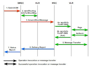
MT Message Flow

MT messages are the messages which are terminated from the mobile phone. The origination of the MT messages is the SMSC. This is somewhat complex process compared with the MO flow which had less number of steps.

The message flow of the MT messages is explained in the picture below.


Step 1
Accept the submission of MT messages to the relevant module in the SMSC. Origination of this messages could be from an applications or could be a MO message.

Step 2
Then for message is to be sent, SMSC access HLR (Home location register) to obtain the location information for a particular user. HLR replies with the relevant information

Step 3
Then the message is transferred to required MSC with the relevant information which would need for MSC to proceed.

Step 4
In step 4, authentication and other information

Step 5
Message is then actually sent to the subscriber. At this stage VLR is updated changing the status of the SMS delivery.

Step 6
Status report of the message is then sent to SMSC.

Step 7
Finally SMSC will update the relevant personal information on HLR and message is then sent to the next step processing

MO Message Flow

The letters MO stands for "Mobile Originated". So MO message is the message which originates from the mobile phone. And even though it is not indicated in the name, destination of the MO messages will be the "Short Message Service Center" (SMSC). From that point onwards SMSC takes care of the message performing routing accordingly.

The message flow of the MO messages is shown in the picture below.


Before subscriber sends the message, access request and authentication is done using the information available on VLR (Visitor location register)

Step 1
In this step, message is sent to the MSC after following the process explained above. MSC (Mobile Switching Center) is responsible for handling all the subscriber events, who are in a particular geographical area.

Step 2
Then the VLR is updated with the relevant information about the MO message. This will be used to obtain the location information about the subscriber who sent the message as well.

Step 3
In this step three, the message is transfered to the SMSC, which handles the rest of the message routing process.

Step 4
SMSC will take relevant routing actions and will be sent to further processing. MO message flow ends up here.

Step 5
The delivery report is sent to the MSC from SMSC, once the SMSC obtains the delivery status of the message.

Step 6
From there onwards MSC will handle the delivery report. Will access VLR and sends relevant delivery status to the subscriber who sent the message. If he's not in his area then will inform back to the SMSC.

The point to note here is that the HLR is not accessed at any point in the MT flow.

Neural networks for the benefit of mankind in health

Mankind has found many ways to make life easy by using IT. Among those inventions Artificial Neural Network has a special place in which it simulates the the biological neural network of human brain.

There are many applications which uses ANNs for the benefit of mankind. Among them Health applications play a leading role because most of the health application's purpose is to predict a probable future outcome which will help humans to avoid it. Neural applications are being used most of the time because of its capability to predict accurately the outcome from the set of past data.

Heart monitoring, ECG analysis is a well known application which uses ANN to identify the pattern of the ECG to recognize an probable condition earlier which will eventually support, supporting the patient with the medical assistance which would be needing in order to overcome the situation.

Another very useful application is prediction of future patients information based on particular geographical location based on the past patient information of that area. This concept is actually implemented by the hSenid Mobile Solutions as IDEWS. (Infectious Diseases Early Warning System). Here the possible patient information of epidemic diseases such as Dengue is informed to relevant authorities, enabling taking precautions. The heart of this system make use of an ANN. And it is actually proven the accurate predictions of ANN.

So anyways there may be so many health related applications that would be developed using ANNs in the future which would become ultimately a life saver.

Friday, September 24, 2010

HLR & VLR

HLR and VLR are two important components in mobile network environment where the basis of mobility depends on these two elements. HLR is the Home Location Register whereas VLR is the Visitor location register.

The main purpose of HLR is to find the location information of a mobile subscriber. For a simple example it is like checking the address of a letter where it should be sent. In this case the problem is, address of the subscriber is not static but dynamic. It changes all the time. So HLR contains the location information of subscribers which helps operators to find where he/she is.

VLR contains information about users in a particular area at a given time. So it is not a permanent storage since the users in a particular area can be switched constantly. This VLR is attached to a particular Mobile Switching Center (MSC) which receives Short Messages (SM) or Calls from operator and distribute it to the final user.

When these two elements are compared and contrasted, HLR is a permanent data storage whereas VLR is a temporary storage. HLR contains all the data about the entire subscriber base of a particular operator whereas at a given time VLR contains information about a subset of the subscriber base unless all the subscribers are in one geographical area. And HLR is built as optimized reading is capable whereas in VLR both the processes reading and writing is optimized.

In conclusion both these elements are vital in mobile networks since the mobility depends on HLR and VLR, specially using HLR.

Thursday, September 23, 2010

Number Portability

Before explaining number portability with a technical aspect will explain using a simple example.

A person using "A" service provider's service and his mobile number starts with 077xxxxxxx. But sevice provider "B" offers very attractive package for a very low amount of charges. And if we are to join "B" we should change our number. But still will u be able to change the provider. For me I cant because the switching cost might exceed the benefit received from changing the service provider. Most of the people today have this problem.

Solution for this could be number portability. What happens in number portability is a particular person will have a one fixed number. And any service provider would be able to get connected and provide services to that number. So switching operator wont be a hazard anymore and it also will lead to more competitive market for mobile service providers. Competitiveness obviously will result in many innovations and subscribers will get the maximum yield out of it.

This concept is somewhat similar to IP V6 concept, in which every individual would be able to own a private IP address of his own with the large address range.

There are practical use of number portability as for today. Even in india it exists. So this is the right time for us to move on and get mixed up with the modern world which is with less hazards.

Wednesday, September 22, 2010

SMSC

In short SMSC is a short message store and forward system.

It provides a facility for users to send SMS between mobile phones or applications. There are three main parts of this process mainly called as Mobile Originated (MO) messages, SMSC and Mobile terminated (MT) messages.

In MO messages what it does is sending message from the mobile phone to SMSC. This will have to follow through many steps such as Base station system (BSS) and Mobile Switching Center (MSC). Visitor Location Register (VLR) and Home Location Register (HLR) will als updated and verifies on the way.

In SMSC as for the definition it routes message and regulate the process.. It applies relevant logics, filtering, validations for the message and follow the necessary procedure. Target of the message could be a another mobile phone or a particular application.

In MT messages again there is a defined path to be followed. First senders location should be found by accessing HLR which contains all the detail of the subscribers. Then once the location of the user is found, it is sent to MSC and there it access VLR for further user detail verification and authentication. Then form MSC it sends the message to the particular mobile subscriber.

If the message is not delivered, HLR is informed to update SMSC when the particular subscriber come live. Message will be stored at MSC. There are two concepts in that case too. Store & Forward and Forward & Store.

In Store and forward message will be stored before checking whether the user is online or not. In the other method forward and store, message is stored once the messaged delivery is failed. There are advantages and disadvantages of both these models.

Saturday, September 18, 2010

Flying When Pregnant

Flying while pregnant is something that our mothers are heavily scared of. But mentioning the summary in short, it is not a something to be worried about provided that the mother and child are in good health and delivery won't take place while on air.

But the fact to remember is most of the airlines have their own restrictions about pregnant ladies travelling. Normally most of the airlines do not allow to travel after 36 months. But that depends on the flight as well. If it is a domestic travel it could be 7 days prior to the due date of 2,3 days.

In one of the studies on pregnancy and air travel, they have revealed that there is a slight increase in miscarriage. But this study was carried out with the flight attendances who stay fairly large amount of their time on air, on average 74 hours per month.

Travelling in first trimester would be little bit difficult for someone as you will be feeling uncomfortable within that period because of pregnancy symptoms such as morning weakness. But anyways in the case of a travel it will be much more comfortable taking some extra sick bags.
The second trimester is somewhat okay to travel as for the studies since your pregnancy symptoms will be less during this period. Risk of miscarriage is significantly lowered.
During third trimester, it is also okay to travel unless the delivery dates are not close by.

Even though it is recommended to travel while pregnant, there is a increased chance of developing a blood clot. But there are actions to be taken as precautions for this. Not crossing your legs, drinking water to keep hydrated, wearing comfortable loose cloths would be some of them.

As a summary again it is not something to worry, travelling while pregnant. But prevention is always better than cure.

Friday, September 17, 2010

Artificial Neural Networks

In short Artificial Neural Network (ANN) is a computational model which represents the behavior of biological neural network.

The base of the ANN is the individual nodes which are composed artificially to represent the behavior of a neurons inside human body. The group or a collection of such a artificial nodes is called as a ANN.

Human biological neural network is a complex element which is used to carry out a specific physiological function. So do the Artificial Neural Network. ANN is also designed as the need of it, to perform the function which is intended to.

The flow of a ANN is it captures an input and then using the set of neural nodes, which is called as the ANN, it classifies the input into different classes and give it away as the output. There are main two types of ANNs based on how the training is carried out which is the most important part in any neural network. Training is of two types, supervised training and unsupervised training. In supervised training weights of each node is adjusted in such a way that the output required is obtained. But in unsupervised learning ANN is allowed to train on it's own. Desired output is not provided. It adjusts according to the changes which is more flexible.

When ANNs are used in applications there may be compromises. Since complicated ANNs use huge amount of memory, there could be a clash between quality and feasibility. It should be properly handled in order to produce a good output.

In many of the applications today, they uses neural networks. Some of they would be Function approximation, regression analysis, time series predictions, classification, pattern recognition, time series analysis, data processing.